The purpose of this document is to identify the information needed for a Modbus device to be able to integrate it into a SCADA system.
Standard Modbus Communication Components for Data Sources
- For Modbus IP: Ip address and port. Port is generally 502 but could be different.
- For Serial / RTU: Baud rate, parity and stop bits and com port
- Polling Rate
Data Point Attributes Needed
-
Slave ID (1-254)
- A device usually has a default ID of 1
- During installation the slave ID of the device is usually set by the installer.
- It’s best to provide the installer with a list of desired Slave IDs and then verify during commissioning.
-
Offset
- This is the register we are to read. Offsets can start at 1 or at 0. In the AES SCADA system offsets start at 0 so sometimes the published register from a device needs to be adjusted by -1.
- Offsets can be represented in different ways. Sometimes as Hex values and sometime the offset will also contain the register type. For example Offsets in the Holding Register range might start with a 4 such as 411001, in the SCADA this would be entered as 11001
-
Type for register or Register Range -
- There are four basic times of Modbus registers which also relate to the “Function Code”
-
Holding Register
- This is the most common type used for all numeric values
- Can be read or write
-
Coil Status
- Used for binary values
- can be read or write
-
Input register
- Read only for numeric values
- Similar to Holding Registers
-
Input Status
- Read only for Binary
-
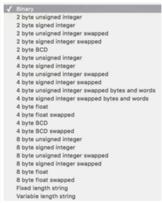
Modbus Data Type
- A standard Modbus Holding Register or Input Register is a 16 bit (2 Byte) value. Often this is not enough so different equipment will utilize multiple modbus registers to hold a larger value. Here is a list of Data Types. Note that these could be referred to in different ways. for example a 4 Byte Signed Integer might be referred to as a 32 bit Integer in equipment documentation.
- For binary values we also need to know what “bit” of the register to look at for the binary value. For this reason a single 16 bit modbus register could represent up to 16 individual binary data points.
- Sometimes the Data Type is inferred by listing the number of registers. For example 2 registers might mean a 4 byte value
- Multiplier or Scale factor
- Modbus register store only whole numbers. For this reason a scale factor often needs to be applied.
- For example a modbus register with a temperature value may read as 723 and a multiplier of 0.1 need to be applied to get the correct value of 72.3 in the SCADA system.
- If the data type is a Float then the multiplier is not needed.
- Read or Write Type
- If this is a read only or a read and write register.
- Formating
- For binary values this would be how 0 and 1 is represented in the SCADA system.
- Example (Off / On) (Normal / Error)
- For Numeric Values this could be how many decimal places
- Units
- For numeric values it’s important to know if it’s a Amps, Volts, Degree F, %, etc.
Other SCADA related information
- Device Name
- This is the name of the device or how all the data points will be grouped.
- Point Name
- This how the register will be referenced to the user within the SCADA system.
- Generally this will be identical between Devices.
- Examples would be “Supply Temperature” Phase A Voltage”
- It’s best to standardise similar names as much as possible
- Logging and Purge Setting
- It’s important to try and keep the database as small as possible to save disk space and increase system performance. Paying attention to the Logging settings and Purge setting is the key way this is done.
- How do we want to Log the values from the Data Point into the database
- Some of the options are:
- All Data
- Each time the point is polled the returned amount will be logged. The amount of data logged will be controlled by the poll rate of the data source
- On Change
- Each time the value of the point changes it will be logged
- This is the best option for set points and often binary points as they only need to log when the value changes
- You can optionally use a tolerance to only log the data point if the value changes by X amount
- Interval
- Often the best choice for Analog data such as temperatures.
- Will log a value on a set interval such as once per minute regardless of how often it is polled.
- There are several ways the Interval can be logged
- Average
- The average of the polls will be logged. If polling is every 5 seconds and Interval logging is set to 1 minute average a 1 minute average of the 5 second polls will be logged
- Maximum
- The maximum value within the interval time frame
- Minimum
- The minimum value within the interval time frame
- Instant
- Logs the exact value it was at the time of logging
- Average
- All Data
- Purge Settings
- How long do we need to keep the data for?
- We can purge the data after 1 month, 1 year, 10 years etc.
To create a Modbus Points List use two spreadsheets with the following columns
Sheet 1
- Data Source Name
- IP address
- Port
- Device Name
- Slave ID
Sheet 2
- Data Source Name
- Device Name
- Point Name
- SlaveID
- Offset
- Register Range
- Data Type
- Multiplier
- Write Status
- Formating
- Units
- Logging
- Purge
- Expected Value
If there are many devices with identical data points it could be sufficient to list just the data points for 1 device and then a sheet with a list of all the devices along with the IP address and Slave ID’s explaining that each device has the listed data points.
Validation Procedures
Generally validation of Modbus registers will be done by reading several registers with exact known values or approximate known values and verify the data is displayed and formatted correctly. A known value might be a serial number for example. An approximate known value might be a Frequency or Voltage reading for Temperature.
As an example when reading a power meter you may have 3-4 voltage reading all in consecutive registers 1,2,3,4 for example. You know approximately what the voltage should be so you read register 1 and you get a good voltage ready, 2 and 3 also give you a good voltage reading but 4 does not. So you read register 0 and you get a good voltage reading. This could tell you that all your offsets are likely off by 1 and need to be adjusted. This is just an example and further validation should be done.
In another example you may read register 100 as a 4 byte float but get back an unrealistic value. So you change the type to a 4 byte float swap and you get a good value. It’s quite likely that the documentation left out details on this.