Overview
The Mango Analog module is a module designed to work with the Mango GT V3. It is intended the be employed in two applications, one would be fitted inside the Mango GT and the other as a stand-alone Modbus device.
The device features eight, 12-bit analog input, each one independently software programmable for 0-5V, 0-10V, 4-20mA, 10k type2 thermistors, low speed digital inputs or counting up to 10Hz rate.
Alternatively, the module PCB can also be used stand alone when fitted to a different base board. This base would have a RS485 transceiver and Modbus connector as well as the 16-way input terminal strip featuring the same connection layout as for the Mango GT V3. In addition, the I2C interface also allows additional I/O to be provided, such as power limited outputs with PWM capability.
The Modbus interface will present a series of registers that can be read and / or written. The first eight are 32bit signed registers for each input, followed by a group of configuration registers. If the input is set for voltage or current, scaling and offset will be provided separately for the 0-5v, 0-10v and 4-20mA ranges. The 10k thermistor range is converted to degrees F before having scaling applied. The scale factor is an unsigned 16bit value and the offset a signed 16bit value. This is applied directly to the ADC count of between 0 and 4095. The scale and offset are in user settable registers and may be programmed to perform the scaling of the ADC value into fixed point engineering units. Two alternative algorithms are provided for scaling and offset, either (ADC*32768/scale) + offset or (ADC*scale/32768) + offset. Both these alternatives are available for the 0-5v, 0-10v, 4 to 20mA and thermistor ranges, allowing each to be scaled differently. As shipped the scaling will be factory set to 0-4096 for all ranges except temperature. These will be set as factory defaults which can be restored for each range separately. A separate bit is the control register for each channel is provided to trigger a restore for each channel. Two special patterns allow copying the current user values to the factory settings and to default all the user values.
If the channels are set for digital inputs or count inputs, the input is treated as low if below 1/3 scale, and high if above 2/3 scale, providing a 1/3 scale hysteresis. In these two modes, the input has a 0-5v range with a 10k pull down. The low speed digital mode will give a 0 result when the input is low and -1 when high.
In the count mode, the count range is 0 to 4,294,967,295 and will accept up to 200 pulses per second. To ensure integrity, the value is saved to non-volatile storage every 5 seconds. In this mode writing to the result register will clear the count. A separate programmable debounce period is provided for each input in counter mode, settable between 0 and 60 seconds in 1ms increments.
Device Connections
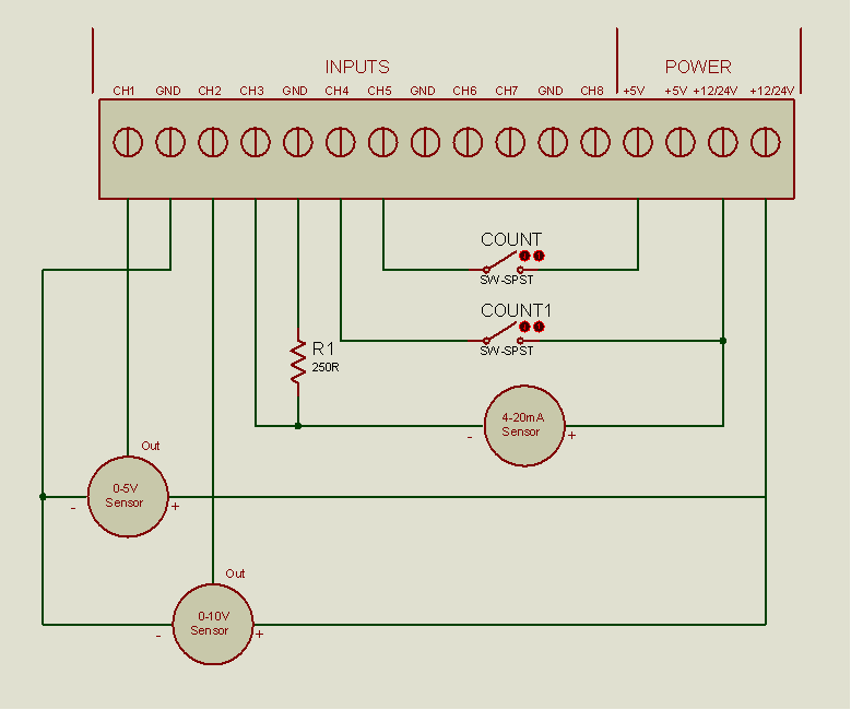
Device inputs are bought out on the MangoGT with a 16-way expansion connector. With the MangoGT oriented so that the connector is on the bottom, pin 1 is on the left. Pin functions as detailed below:
Device Configuration
![]()
In your MangoGT under Administration > Admin home you will find the Mango IO Tools in the Utilities section.
Use the Mango IO Tools module for managing and configuring your attached Mango IO Modules. These modules are either included inside your MangoGT or connected externally. For more information on the Mango IO Modules please visit:
Selecting Comm Port
If you purchase a MangoGT with the internal Analog Input module, you will have the Data Source and Data Points already populated. The Data Source specifies the Comm Port being used for communications. The Data Source Named “IOBoard” uses the comm port connected to the Internal Analog Module. The default Slave ID is 1.
You would only change the Selected Data Source or Slave ID if you were configuring external IO Modules.
Functions:
There are four tools contained within the Mango IO Tools Modules
Scan
The scan feature will have Mango query a network for any MangoIO Devices and displays their Type, Serial No, Manufacturing Date, hardware and software versions.
Configure
The Configuration tool is the most important and allows you to configure each channel of the Input Module individually.
Calibration
The Calibration tab allows you to perform a calibration to a known voltage reference. Factory calibration is done before shipping the units so this should not be needed.
I/O
The I/O Tool is an advanced tool that acts as a console to the IO device allowing a developer to send and receive commands.
Firmware
The Firmware upload tool allows the user to upload a new firmware file and have it sent to the device.
Configuring the Analog Channels
Before any configuration can be done, first click the “READ FROM DEVICE” button to load in its parameters.
You can configure each Channel with the following properties:
Mode
You can select the type of sensor you are using from 0-5vdc, 0-10vdc, 4-20ma or thermistor. Note that 4-20ma input signals require a 250 ohm 1/2W 0.1% resistor between the input and ground terminal.
If a channel is set to digital inputs or count inputs, the input is treated as low if below 1/3 scale, and high if above 2/3 scale, providing a 1/3 scale hysteresis. In these two modes, the input has a 0-5v range with a 10k pull-down. The low-speed digital mode will give a 0 result when the input is low and -1 when high. In the count mode, the count range is 0 to 4,294,967,295. In this mode writing to the result register will clear the count.
Raw Value
The raw value is a value from 0-4096 which is the full resolution of the 12 bit Analog to Digital converter.
Data Point Value
These are the Data Points in Mango that will be reading, logging and displaying the data from the IO Board. This displays the value being recorded and displayed in Mango after the raw value has been scaled.
Low and High Scaling
The raw output of the Analog to Digital converter is a value from 0-4096 which represents a 12-bit resolution. The Low Scale Value and the High Scale value represents the how you want your data to be represented. For example if you have a 0-100psi pressure sensor and want the values to be recorded with 1 decimal place you would enter Low Scale Value = 0, High Scale Value = 100, Decimal Places = 1, and Suffix of psi.
Digital Input Mode
Changing to Digital Input Mode changes the Data Point from numeric to Binary and the logging from a 1 minute average to log when value changes. It is important to know that changing the data type of a Data Point, such as from Numeric to Binary will cause all the history to be deleted.